
The Memory Protection Unit, or MPU for short, is an unloved child, although it is very important and helpful. The reason for the resentment lies in the nature of the matter, the MPU is not constructive, but uncovers software malfunction and prevents worse. It does not ensure that SW suddenly works, but rather the contrary, you spend hard work to get SW running under MPU control, that worked nicely without the MPU. So why should I do this? Because the MPU makes the SW safer and more stable and because the MPU is mandatory in safety-relevant applications. In order to simply the complex configuration, two free tools are presented here. The first is an Excel-based graphical MPU code generator and the second is a piece of C-code, MPU info, which outputs the settings of the MPU. Unfortunately many debuggers are not capable of doing this properly. With the introduction of the Armv8-M architecture, a new Protected Memory Software Architecture PMSAv8 has also been introduced, which means that the MPU of the v8-M is not backwards compatible with the v7-M. The different MPUs make the matter even more complex, … unloved child. Don’t worry, the two tools make life easier, as we don’t have to dive into the individual register details
Memory Protection Unit
The MPU is a hardware component integrated in the Arm Core that is located in the bus system between the CPU and memory controller and monitors access. Whenever the core reads or writes an address, this access is controlled by the MPU. This applies to accesses to flash, RAM, peripherals, both internally and externally, and even to the tightly coupled memory. The cache controllers are even orchestrated by the MPU, i.e. the MPU determines which memory areas are cached and which cache policy is applied. The MPU is programmed by configuring regions.
MPU Regions
Regions are storage areas for which access rights and storage attributes may be defined. If access is not permitted by a suitable region, a memory fault is triggered. This means that the processor executes an exception, similar to an interrupt, in which an error handling is executed and usually also a reset is triggered. Since the access rights not only distinguish between reading and writing, but also between privileged and unprivileged access, several scenarios can be realized in which, for example, applications can be prevented from accessing OS data or a stack overflow may be detected.
MPU Configuration
In order to adapt the MPU to the respective application, the regions must be programmed. For this purpose, two 32-bit registers are available for each region. In a 3rd register, the Region Number register is used to determine which region can currently be configured. For this purpose, the two registers of the selected region are mapped to a fixed pair of addresses. In a 4th, read only register, the MPU-Type register, The number of implemented regions may be read out. In v7-M architecture there are 0, 8 or for some Cortex-M7 optional 16 regions. In the v8-M architecture, this can be 0, 4, 8, 12 or 16 regions. In addition, a v8-M controller with trust zone has two MPUs and thus two sets of registers, one set for the Secure and one for the non-secure world. The bits within the registers differ substantially between the v7-M and v8-M architecture and are not compatible to each other. Those details go beyond the scope of a blog post. The Excel tool mentioned at the beginning does the detailed work for us. So we can conveniently configure the regions via the graphical interface of the Excel tool and receive as a result C-code, which populates the regions with the selected values. Since the 2 x 32-bits of the registers per region were not sufficient in the v8-M architecture, since the more flexible definition of the region addresses take too much space, additional attribution-indirection registers MAIR were added. This are 8x 8-bit registers, with index 0-7, which are combined into two 32-bit registers. Each region contains such an index in 3 bits and thus points to one of the attribution indirections. But don’t worry, this configuration is also handled via the Excel tool.
There are two different Excel tools, for
- v7-M, i.e. Cortex-M0+, M3, M4, M7 and
- v8-M, i.e. Cortex-M23, M33, M35P, M52, M55 and M85.
EXCEL MPU-Configurator
Über die Links
- www.tnms.de/mpu or
- www.tnms.de and the Menu Entry Downloads->MPU Configurator
the two versions of the Excel tool are available for download free of charge.
Input values for the configuration of the MPU are entered in the Excel sheet “CONFIG”. Excel allows the input of values for 16 regions, even if only less are realized on the chip. According to Arm Specification, the behaviour of the MPU is undefined when values are configured for non-existent regions. Therefore, in the generated macro MPU_CONFIG_REGION(num), it is checked at runtime whether the respective region exists and only then the entered values are also programmed into the MPU, thus avoiding a potentially undefined state.
#define MPU_CONFIG_REGION(num)\
  if( num < ((MPU->TYPE & MPU_TYPE_DREGION_Msk)>>MPU_TYPE_DREGION_Pos)) \
  {\
    MPU->RNR  = (num & MPU_RNR_REGION_Msk);\
    MPU->RBAR =  ARM_MPU_RBAR(num,BASE_REG##num);\
    MPU->RASR = (ARM_MPU_RASR_EX(XN_REG##num, PERM_REG##num, TEXSCB_REG##num,\
    SRD_REG##num,SIZE_REG##num)&~((ENABLE_REG##num)?0:MPU_RASR_ENABLE_Msk));\
  }
Figure 1: MPU_CONFIG_REGION Macro in Sheet CODE for armv7m_mpu_config.h
Figure 1 shows the Macro MPU_CONFIG_REGION, which is called for each region when the defined CONFIG_REGn is set to 1 and the MPU has at least n regions. The definition is set via the graphical user interface shown in Figure 2 by the first checkbox “Configure Region” displayed in Figure 2 in cell C7 in green and in cell C26 in red.
The last entry of a region is to enter a value for “TEX Cache Buf” that is required to control a potentially existing cache. Since in the armv7-M architecture a cache is only provided for the M7, you do not have to worry about these more complex settings in projects of the M0+, M3, M4. The defaults published by Arm for simpler cases are selectable via the top entries to ease the configuration (see Figure 3).
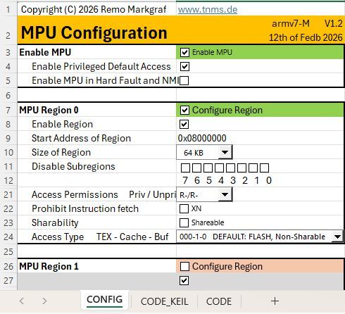
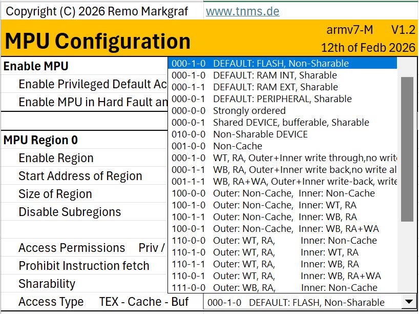
Figure 2: Graphical User Interface armv7m_MPU
Figure 3: Pulldown for TEX-C-B with Defaults
// MPU Region 0 ********************************
#define CONFIG_REG0  1
#define ENABLE_REG0  1
#define BASE_REG0    0x08000000
#define SIZE_REG0    15
#define SRD0_REG0    0
#define SRD1_REG0    0
#define SRD2_REG0    0
#define SRD3_REG0    0
#define SRD4_REG0    0
#define SRD5_REG0    0
#define SRD6_REG0    0
#define SRD7_REG0    0
#define SRD_REG0     (SRD0_REG0 | SRD1_REG0 | SRD2_REG0 | SRD3_REG0 |\
                      SRD4_REG0 | SRD5_REG0 | SRD6_REG0 | SRD7_REG0)
#define PERM_REG0    6
#define XN_REG0      0
#define SHARE_REG0   (0<<MPU_RASR_S_Pos)
#define ACCESS_REG0  0x020000
#define TEXSCB_REG0  (ACCESS_REG0 | SHARE_REG0)
Figure 4: In Sheet CODE implemented Defines for Region 0
Figure 4 depicts the definitions of a region with values set by the graphical user interface. The values are used in the previously MPU_CONFIG_REGION Macro and the MPU is configured accordingly. The MPU_CONFIG_REGION Macros are called by the inline function MPU_Init() shown in Figure 5.
static inline void MPU_Init(void)
{
#if defined(__MPU_PRESENT) && (__MPU_PRESENT == 1U)
  #if defined (CONFIG_REG0) && (CONFIG_REG0 == 1U)
    MPU_CONFIG_REGION(0);
  #endif
  …
  #if defined (CONFIG_REG15) && (CONFIG_REG15 == 1U)
    MPU_CONFIG_REGION(15);
  #endif
  #if defined (MPU_INIT_CTRL_ENABLE) && (MPU_INIT_CTRL_ENABLE== 1U)
    ARM_MPU_Enable( MPU_INIT_CTRL_BITS );
  #endif
#endif //__MPU_PRESENT
}   //MPU_Init (void)
Figure 5: In Sheet CODE generated function MPU_Init()
The CODE_KEIL sheet contains the same defines and macros, only additional comment lines are added, which control the graphical editor integrated in Keil μVision. Thus, it is possible to graphically edit the values of the Defines via the editor without the Excel tool in the project. The many comment lines make the code very confusing and therefore there is the sheet CODE that you can use if you do not work with Keil μVision. Figure 6 shows an example of how the graphical editor of armv7m_mpu_config_keil.h looks like in Keil μVision.
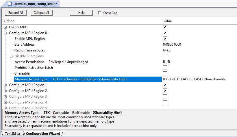
Figure 6: armv7m_mpu_config_keil.h in Keil µVision
To use the Excel Configurator, enter the values for the required regions in Excel, copy the entire content of the CODE or CODE_Keil sheet to the editor of your development environment and name the file, for example, armv7m_mpu_config.h. You then include it in your main.c and call the MPU_Init() function within main(). An example of such a main() function is shown in Figure 7.
Armv8-M MPU Configurator
The Armv8-M MPU Configurator (see Figure 8) differs from the v7-M in:
- Additional sheet CONFIG_NS for the non-secure MPU
- Changed Regions Parameters
- Graphical settings for the Attribution Indirection Register below the regions
 1      #include "board.h"               //depends on your environment
 2      #include "armv7m_mpu_config.h"   //resp. "armv8m_mpu_config.h"
 3      #include "armv7m_mpu_info.h"     //resp. "armv8m_mpu_info.h"
 4
 5      int main(void)
 6      {
 7            //
 8            // initialize board
 9            //
10
11           // check working printout
12           const char* str="Hello World :-)\r\n";
13           while(*str != '\0')
14                  putchar(*str++);
15
16           MPU_Init();
17           MPU_Info();
18
19           // loop forever
20           while( 1)
21           {
22           }
23     }
Figure 7: Code Example for main.c
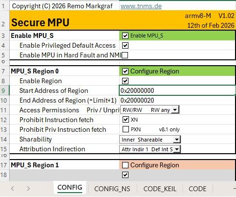
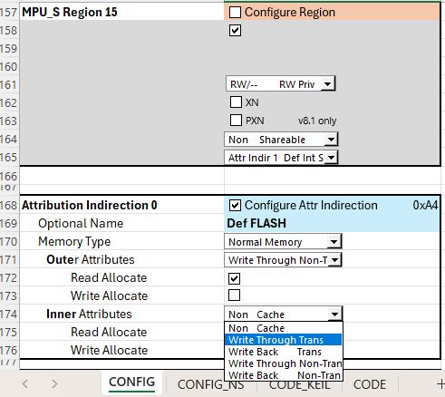
Figure 8: GUI for armv8m_MPU
Figure 9: MAIR Register settings below Regions
MPU Info
Those who do a lot make many mistakes, so it is essential to control what settings you have given to the MPU. A debugger is very suitable for this if it can display the MPU configuration properly. Unfortunately, this is not the case with most debuggers. A simple output of the settings via a terminal program or the debug console is a very helpful tool in this case. Figure 10 shows the exemplary output of relevant settings of a v7-M MPU with 8 regions. The necessary code for the MPU_Info() is also available for download free of charge and consists of the sources
for v7-M architecture
- armv7m_mpu_info.h and
- armv7m_mpu_info.c
for the v8-M architecture
- armv8m_mpu_info.h and
- armv8m_mpu_info.c
The sources are available for download on the same page as the Excel tool:
The call of the MPU_Info() function is displayed as part of the main.c Source in Figure 7. In Figure 11, in the case of the armv-8m, both the Secure and the Non-Secure settings are output if a TrustZone is present and MPU info() is called from the Secure world. Otherwise, only one MPU is output.
For output, the sprintf() function is used and the filled string buffer is output character by character via the Macro PRINTCHR. For easy migration, the line is located at the top of the mpu_info.c source
#define PRINTCHR(c) putchar(c)
and can be easily adapted to the respective environment for adaptation.
*** MPU_Info START
      MPU is present
  _________________________
  |                       |
  |       MPU             |
  |_______________________|
  | MPU Settings
  |   is enabled
  |   is NOT active during HF & NMI
  |   is configured with a default Region when privileged
  | MPU Regions
  |   supports 8 Regions
  |   may overlap and need to be aligned to their size
  |   have priorities, 0 is lowest, 7 is highest priority
  |   No_E_Start______Size__XN_SRD______Pr/Un_TEX___S_C_B
  |    0 E 0x08000000  64KB -- -------- R-/R- 0b000 - C - Flash
  |    1 E 0x20000000 512B  XN -------- RW/RW 0b000 S C - Internal RAM
  |    2 E 0x48028000   2KB XN DD-DDD-D RW/RW 0b000 S - B Peripheral
  |    3 - 0x00000000   0   -- -------- --/-- 0b000 - - -
  |    4 - 0x00000000   0   -- -------- --/-- 0b000 - - -
  |    5 - 0x00000000   0   -- -------- --/-- 0b000 - - -
  |    6 - 0x00000000   0   -- -------- --/-- 0b000 - - -
  |    7 - 0x00000000   0   -- -------- --/-- 0b000 - - -
  |________________________
--- MPU_Info END
Figure 10: Example Output of MPU_Info() for Armv7-M M0+, M3, M4, M7
*** MPU_Info START
      MPU is present
  _________________________
  |                       |
  | SECURE MPU_S          |
  |_______________________|
  | MPU_S Settings
  |   is enabled
  |   is NOT active during HF & NMI
  |   is configured with a default Region when privileged
  | MPU_S Regions
  |   supports 8 Regions
  |   may NOT overlap and need to be aligned to 32 byte
  |   have NO priorities
  |   No_E_Start______Limit______XN_PXN_Pr/Un_Share_A
  |    0 E 0x20000000 0x2000001F XN --- RW/RW Inner 1
  |    1 - 0x00000000 0x0000001F -- --- RW/-- none  0
  |    2 - 0x00000000 0x0000001F -- --- RW/-- none  0
  |    3 - 0x00000000 0x0000001F -- --- RW/-- none  0
  |    4 - 0x00000000 0x0000001F -- --- RW/-- none  0
  |    5 - 0x00000000 0x0000001F -- --- RW/-- none  0
  |    6 - 0x00000000 0x0000001F -- --- RW/-- none  0
  |    7 - 0x00000000 0x0000001F -- --- RW/-- none  0
  | MPU_S Attribution Indirection
  |   No_Val__Type___OuterCache_InnerCache
  |    0 0xAA Normal WT_nT_RA   WT_nT_RA
  |    1 0xAA Normal WT_nT_RA   WT_nT_RA
  |    2 0x00 Device nGnRnE
  |    3 0x00 Device nGnRnE
  |    4 0x00 Device nGnRnE
  |    5 0x00 Device nGnRnE
  |    6 0x00 Device nGnRnE
  |    7 0x00 Device nGnRnE
  |________________________
  _________________________
  |                       |
  | NON-SECURE MPU_NS     |
  |_______________________|
  | MPU_NS Settings
  |   is NOT enabled
  |   is NOT active during HF & NMI
  |   is configured with NO default Region when privileged
  | MPU_NS Regions
  |   supports 8 Regions
  |   may NOT overlap and need to be aligned to 32 byte
  |   have NO priorities
  |   No_E_Start______Limit______XN_PXN_Pr/Un_Share_A
  |    0 - 0x00000000 0x0000001F -- --- RW/-- none  0
  |    1 - 0x00000000 0x0000001F -- --- RW/-- none  0
  |    2 - 0x00000000 0x0000001F -- --- RW/-- none  0
  |    3 - 0x00000000 0x0000001F -- --- RW/-- none  0
  |    4 - 0x00000000 0x0000001F -- --- RW/-- none  0
  |    5 - 0x00000000 0x0000001F -- --- RW/-- none  0
  |    6 - 0x00000000 0x0000001F -- --- RW/-- none  0
  |    7 - 0x00000000 0x0000001F -- --- RW/-- none  0
  | MPU_NS Attribution Indirection
  |   No_Val__Type___OuterCache_InnerCache
  |    0 0xAA Normal WT_nT_RA   WT_nT_RA
  |    1 0x00 Device nGnRnE
  |    2 0x00 Device nGnRnE
  |    3 0x00 Device nGnRnE
  |    4 0x00 Device nGnRnE
  |    5 0x00 Device nGnRnE
  |    6 0x00 Device nGnRnE
  |    7 0x00 Device nGnRnE
  |________________________
--- MPU_Info END
Figure 11: Example Output of MPU_Info() for Armv8-M
M23, M33, M35P, M52, M55, M85